
- Arduino camera shutter tone how to#
- Arduino camera shutter tone pdf#
- Arduino camera shutter tone install#
- Arduino camera shutter tone driver#
Switched over to a different computer, and the software worked, but the LED still didn't turn on. Turned out that my Arduino IDE installation was corrupted on my main computer, and wasn't properly uploading the testing software on the Arduino.

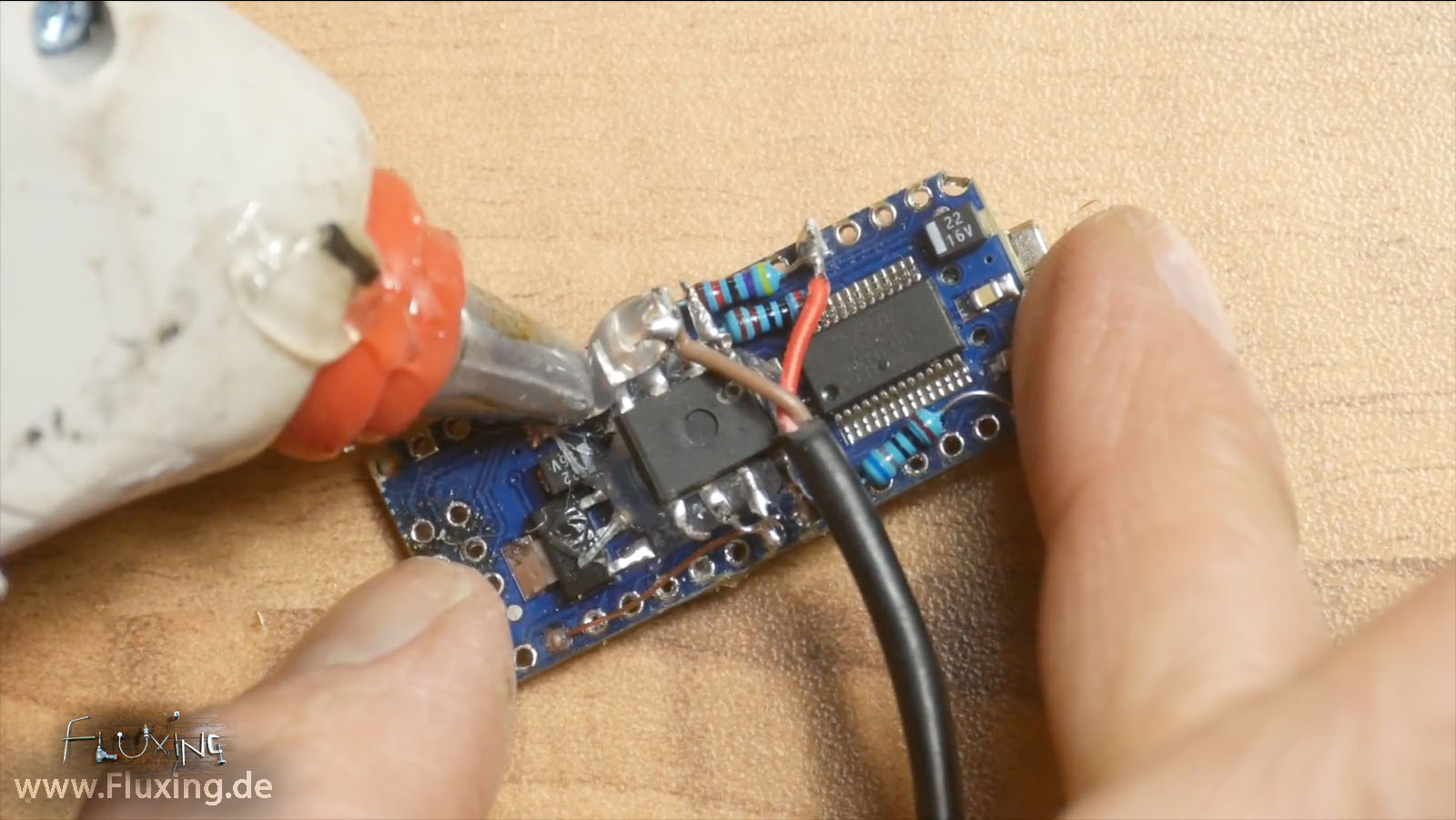
Then, the LED that was supposed to light up, didn't. I'll have to fix that in the instructions. Removed the offending components and solder, and it fit with no shorts:įortunately, it was possible to re-route the offending connection so that it was well clear of the USB shield.

So there were solder blobs and wires that shorted out on the USB shield, and prevented the shield from fully seating into the Arduino: I got fooled by the existence of component holes in a place where no components should go.
Arduino camera shutter tone install#
Turns out I had forgotten that a section of the shield board sits flush against the ground shield of the Arduino's USB power, so you can't install any components there.
Arduino camera shutter tone driver#
First, I installed the MOSFET driver shield board on the Arduino Mega, and discovered that a clever enhancement I had thought up not only prevented the board from seating properly, but shorted out the power supply. You know that feeling you get when you put a whole bunch of system components together, and they work perfectly the first time? Yeah, me neither.
Arduino camera shutter tone how to#
Full instructions will be written up, including how to install it in the control box. At a minimum, it will show how far along in the process you are, and how much time is left. Still have to figure out which parameters to display and how, but I'll get that working when the system is fully assembled. Sometimes it really is the hardware's fault.Īnyway, here's a couple of pics of the display in action plugged into the MOSFET driver shield that's part of the new RTI system being built. Grabbed the Arduino that will be controlling the current build being documented, uploaded the code, and tested it. Connected it back up to the first Arduino, and it worked fine. Spent an hour debugging code, checking connections - nope. Then hooked it up to one of my older RTI systems, and modified the control code to add display support. Connected the board to a spare Arduino Mega I had lying around, uploaded the test code (after a few modifications), and it worked fine. Adafruit has a nice tutorial on their use, along with sample code. I've been thinking about adding a more useful feedback tool, and finally broke down and bought one of those little 0.96" 128 x 64 I2C OLED displays that you can pick up for less than $10 if you look. Not a lot of information, and also not really necessary, since I get a shutter sound from the camera indicating that it's firing, which indicates that things are working. On my previous RTI systems, the only feedback I get from the controller during the operation is a "beep" when each LED is turned on. Hackaday deadline for the 2016 competition is October 5th, so I have a little incentive :-).
Arduino camera shutter tone pdf#
I also hope to meld all the instructions and relevant logs into a single downloadable PDF that should be a more helpful construction guide than having everything online.

With luck all the build instructions will be up by September 20th, and all calibration/operation instructions done in the following week. Getting the project documentation finished will be my top priority for the rest of this month. Once I'm back though, instructions will come fast and furious. Otherwise, they'll have to wait until next weekend or early next week - heading out for 5-8 days of fieldwork (depending on weather) in the boonies. If I hear from Hackaday by tomorrow that they've implemented a fix, I'll post all those up. I have four more instruction steps written up, waiting for a fix for the "Error 413" problem I'm currently getting when I try to post a new instruction.


 0 kommentar(er)
